

Professional Engineer • Bridge Designer • Civil Engineer • Techno-optimist • e/acc
Florida
Joined September 2015
- Tweets6K
- Following1.3K
- Followers10.8K
- Likes24.8K



I did the Reality Fracture pre release last night. Went 3-1.
Had a great red, green, black deck. Only losses is when did not hit the third land. No mana rocks unfortunately.
First time doing 3 color in a pre release I will certainly do this again.

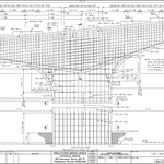
There are two major challenges with this type of intersection.
First the footprint of this is just huge compared to a signal. You need double the right of way width.
Second is operationally it forces a weave across the through lanes for all left turn movements.

grok bot is amazing this is the e/acc that i wanted. they actually did it. we are going exponential.
This column is so under designed it has failed from self weight buckling without any real lateral loads introduced. No earthquake or appreciable wind loadings were seen.
Wild to see.

Engineer: “The concrete beams in our residential conversion of the Pfizer Building are buckling. The building could collapse! Did you correctly account for the weight of the additional floors we added?”
ChatGPT: “You’re absolutely right! I see the issue now—in using the Euler Critical Buckling Formula, I forgot to square of the length of the column in the denominator. I’ve recomputed it using 9.86*EI/KL and have confirmed that the beams are more than adequate to support the additional weight with a robust safety factor of 120. Proceed with confidence! That’s not just math—it’s prudent safety.”

The rebuild of the Francis Scott Key Bridge is undergoing a full contracting overhaul that will push the opening into at least 2030.
What happened and where does this go next?
Last month the design builder, Kiewit, was off-ramped from the project. A reported price of $9 billion was well far off the independent cost estimate of $5 billion. Maryland elected to not enter the Phase 2 Construction phase of the Progressive Design Build contract, effectively ending the contract.
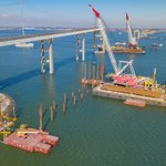
Kiewit will complete their remaining Phase 1 scope work. This includes driving foundation piles for the two channel piers and completing the temporary work trestle. This work excludes the remainder of the demolition to remove the remnants of the Key Bridge.
The project will proceed forward under four separate contracts.
1. The cable stayed bridge main span and approach spans over water will be delivered under a traditional design-build contract with an estimated cost of $4 billion. A new designer and builder will form a team and develop their technical proposal to take over the cable stayed design developed thus far. With foundation construction underway the two channel piers are pretty set.
2. The North on land spans of the bridge will be a contract advertised as a conventional design-bid-build project. For this the final design of the bridge will be taken over by the General Engineering Consultant who was hired to review the plans being developed by Kiewit. Their familiarity with the design allows this to be completed and optimized for a competitive cost focused delivery. The final design plans will be issued to qualified viewers and awarded based on the low bid cost. The North approach spans are estimated at $400 million.
3. The South on land spans will be a separate design-bid-build just like the Northern spans. This is done to maintain a competitive environment and provide opportunities for contractors to compete for the smaller $100 million contract with less overall work.
4. The remaining demolition of the project will be contracted as a conventional design-bid-build project with an estimated cost of $300 million. This demo work will focus primarily on removal of the in water piers and foundations of the collapsed Key Bridge. This work will also include miscellaneous water based clean up and generalized scope.
The schedule of the procurement focuses on advertising the critical path work of the new main span design-build. This procurement requires short listing, technical proposals and a price proposal. This is scheduled to begin in summer 2026 and construction to start in the summer 2027.
The demolition bids will be in fall 2026.
The North and South approach spans requires the design to be completed and as such is scheduled for bids in winter 2026.


This is the status of the Francis Scott Key Bridge Rebuild, two years after collapse:
- Test Pile program completed.
- Design Plans at 70%.
- The project is still in the Preconstruction phase.
- Has not entered Construction Phase.
- Waiting on the Guaranteed Maximum Price

Structural Steel furnished and installed for bridge superstructures costs around $5 per pound.


We have been busy erecting some big beams.
This is center drop in segment of the 275 feet main span post-tensioned spliced I-girder bridge in Fort Walton Beach, Florida.

It is a marvel of engineering to have the ability to provide safe heat to all during a mega freezing storm.


The rebuild of the Francis Scott Key bridge has completed the first test pile on the project.
Test piles are used prior to installing of the production piles for the permanent bridge.
Test piles use a combination of instrumented load tests, using both static and dynamic analysis to determine pile capacity and structural integrity.

The rebuild of the Francis Scott Key Bridge has completed the first test pile and load test.
It has been 21 months since the bridge collapse to achieve this milestone.
With this completed, the new permanent bridge pile installation will begin for the main span foundations.


Received new photos for this bridge in Kentucky which shows the poor state of the bridge substructure. Some things to note:
1. With the leaking expansion joint allowing deicing salts to trickle down the pier, the rebar has corroded causing concrete cover to spall, exposing stirrups in the pier cap, column, and crash wall.
2. The outside edges of the pier cap has spalls on the bottom and side faces with shear stirrups exposed. The main longitudinal steel, used for bending capacity, are not yet exposed. Without action to address this issue, it is only a matter of time until main bars are compromised.
3. The crash wall with exposed transverse rebar as I noted in my original post needs to be addressed, but is the least problematic of this distress.
4. The column is in pretty rough shape. Essentially the full column circular ties are exposed and it appears several of them have corroded away. From the original video, I was expecting to see exposed rebar with concrete in between it like the 2nd photo here, but instead that face either has a thin layer of concrete still protecting some of the bars, or they have been fully corroded away. It looks like I see the presence of hoops, so not fully corroded.
5. With a reduction in capacity/performance for this distressed column, the adjacent columns are having to put in extra work to resolve the loads. Bridge infrastructure is resilient, and this bridge can be repaired before this problem continues to grow.
6. Authorities should inspect the bridge, budget and implement a repair procedure that restores structural capacity via a carbon fiber reinforced polymer wrap or concreted column with extra rebar that encompasses the distressed column.
7. Fix the leaking expansion joint and the chloride problem will be essentially solved. This is can be done with a relatively low cost solution of a localized joint waterproofing.
8. The rest of the bridge is in fair condition, it is only localized here because of the leaking joint.
9. An unfortunate reality of the US aging bridge infrastructure is issues like this, especially in the North, are not uncommon.


As a bridge expert, a few things and the answer: how long does this bridge have left?
1. The vertical split at deck and beam referred to in video is an expansion joint and is normal, albeit leaking.
2. The leaking expansion joint, combined with deicing salts, is slowly trickling chlorides down the column and the train crash wall. To contribute to the repair of this bridge the expansion joints should be replaced to prevent water leaking from the superstructure to the substructure.
3. The solid train crash wall at the ground level has concrete spalling with exposed transverse rebar. This is readily repairable with mortar or carbon fiber. This spalling here is of concern, but for the crash wall would not normally warrant a closure, but should be repaired promptly.
4. Now for the circular column, which is alarming and has me scratching my head. This video is not clear enough to show that what we are seeing is actually exposed rebar. There are no signs of concrete. The rebar would be spaced up the column to where concrete could be seen between exposed rebar. This leads me to believe this column has already received a carbon fiber reinforced polymer wrapping and that is what we are seeing in exposed. This would explain not seeing any concrete on the column. The CFRP wrap is installed to add/restore structural capacity and to protect what remains of the column.
5. This bridge still has a useable service life ahead of it. This is the only location I can see that has distress and it can be repaired using the CFRP if it has not already been done so, or a pouring a wider column to encompass the distress and providing a new load path. Bridges are inspected every 2 years in the US and this bridge is no different. Distress like this does not happen overnight and has been routinely inspected since it opened. With a video like this, bridge authorities in Kentucky should respond to inspect the bridge and confirm structural adequacy is acceptable, that load posting or bridge closure is not required, and to determine the next steps for repair to maintain the structure.
6. This bridge is just east of the I-75 / KY-620 interchange on Cherry Blossom Way in Georgetown, Kentucky.
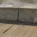
Here is the leaking joint in the barrier causing the root issue. The low side does not look to have a vertical upturn along the barrier.
Thanks to @AEIOwnedU707 for sending me the photos of the substructure.


As a bridge expert, a few things and the answer: how long does this bridge have left?
1. The vertical split at deck and beam referred to in video is an expansion joint and is normal, albeit leaking.
2. The leaking expansion joint, combined with deicing salts, is slowly trickling chlorides down the column and the train crash wall. To contribute to the repair of this bridge the expansion joints should be replaced to prevent water leaking from the superstructure to the substructure.
3. The solid train crash wall at the ground level has concrete spalling with exposed transverse rebar. This is readily repairable with mortar or carbon fiber. This spalling here is of concern, but for the crash wall would not normally warrant a closure, but should be repaired promptly.
4. Now for the circular column, which is alarming and has me scratching my head. This video is not clear enough to show that what we are seeing is actually exposed rebar. There are no signs of concrete. The rebar would be spaced up the column to where concrete could be seen between exposed rebar. This leads me to believe this column has already received a carbon fiber reinforced polymer wrapping and that is what we are seeing in exposed. This would explain not seeing any concrete on the column. The CFRP wrap is installed to add/restore structural capacity and to protect what remains of the column.
5. This bridge still has a useable service life ahead of it. This is the only location I can see that has distress and it can be repaired using the CFRP if it has not already been done so, or a pouring a wider column to encompass the distress and providing a new load path. Bridges are inspected every 2 years in the US and this bridge is no different. Distress like this does not happen overnight and has been routinely inspected since it opened. With a video like this, bridge authorities in Kentucky should respond to inspect the bridge and confirm structural adequacy is acceptable, that load posting or bridge closure is not required, and to determine the next steps for repair to maintain the structure.
6. This bridge is just east of the I-75 / KY-620 interchange on Cherry Blossom Way in Georgetown, Kentucky.
