






Why Current Transformer and Voltage Transformer are both called Instrument Transformers? forumelectrical.com/magnetiz…
#currenttransformer #potentialtransformer #PT #CT #transformers #electrical

Residential Switch and Socket Wiring Diagram forumelectrical.com/switch-b…
Electrical Connections and Wire Colour Codes
The diagram illustrates a typical residential electrical installation showing the wiring connections for switches and socket outlets, including phase (line), neutral, and protective earth conductors.
It demonstrates commonly used conductor colour-coding conventions in South Asian and British-influenced electrical installations. Actual wire colours must be verified against the applicable national wiring regulations and installation standards, as colour codes may vary by country and installation age.
#ResidentialWiring #ElectricalWiring #SwitchAndSocketWiring #WireColourCode #PhaseNeutralEarth #ElectricalInstallation #SocketOutlet #ElectricalSafety #DomesticWiring #EarthingSystem #ElectricalStandards #electricalengineering
forumelectrical.com/switch-b…

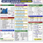
Short-Circuit Current Calculation at Generator Terminals According to IEC 60909-0:2016 forumelectrical.com/how-to-r…
Calculating the initial symmetrical short-circuit current (Ik") at synchronous generator terminals requires consideration of the generator's subtransient reactance, armature resistance, rated parameters, and applicable IEC 60909 correction factors.
This calculation establishes the initial symmetrical short-circuit current used for generator fault-level assessment and subsequent short-circuit calculations at downstream switchboards.
1. Required Generator Parameters
- Rated Apparent Power (Sn)
- Rated Terminal Voltage (Un)
- Rated Power Factor (cos φ)
- Direct-Axis Subtransient Reactance (Xd")
- Armature Resistance (Ra), where applicable
- Voltage Factor (c)
2. Short-Circuit Calculation Procedure
The calculation involves the following steps:
1. Calculate the generator base impedance.
2. Convert subtransient reactance (Xd") from per-unit (p.u.) to ohms.
3. Convert armature resistance (Ra) from per-unit to ohms, where required.
4. Determine the applicable generator correction factor (KG).
5. Calculate the corrected generator internal impedance.
6. Apply the IEC 60909 generator correction factor.
7. Determine the initial symmetrical short-circuit current (Ik") at the generator terminals.
3. Engineering Application
The calculated Ik" is essential for:
- Generator short-circuit withstand assessment.
- Circuit breaker interrupting-capacity selection.
- Switchgear short-circuit rating verification.
- Protection relay coordination and fault-current studies.
- Downstream distribution network fault-level calculations.
A complete worked example using alternator manufacturer data demonstrates the calculation methodology and application of IEC 60909.
#ShortCircuitCalculation #IEC60909 #GeneratorProtection #ShortCircuitCurrent #InitialSymmetricalCurrent #SubtransientReactance #GeneratorImpedance #FaultLevelCalculation #PowerSystemAnalysis #ElectricalEngineering #Alternator #CircuitBreakerSizing #SwitchgearDesign #ProtectionCoordination #PowerSystemProtection
forumelectrical.com/how-to-r…

Suzlon Secures 250 MW Wind Power Project Expansion from Torrent Green Energy forumelectrical.com/suzlon-e…
Suzlon is expanding its renewable energy portfolio through an additional 250 MW wind power project awarded by Torrent Green Energy. The project strengthens India's wind energy generation capacity and supports the expansion of utility-scale renewable energy infrastructure.
#Suzlon #TorrentGreenEnergy #WindPower #WindEnergy #RenewableEnergy #WindPowerProject #250MW #CleanEnergy #GreenEnergy #PowerGeneration #WindTurbines #SustainableEnergy #EnergyTransition #IndianRenewableEnergy #electricalengineering
forumelectrical.com/suzlon-e…

Why is an open CT secondary and a shorted PT secondary dangerous? forumelectrical.com/magnetiz…
ANSWER IN COMMENT
Follow Us On:
Website: forumelectrical.com
Facebook: facebook.com/profile.php?id=…
LinkedIn: linkedin.com/showcase/911302…
Twitter: xitter.cf/ForumEIectrical
Pinterest: ru.pinterest.com/ForumElectr…
WhatsApp Channel: whatsapp.com/channel/0029VbB…
Telegram: t.me/F0rumElectrical
#ElectricalSafety #CurrentTransformer #PotentialTransformer #CT #PT #ElectricalEngineering #ElectricalTechnician #PowerSystems #ElectricalMaintenance #SafetyFirst #ElectricalSafety #CurrentTransformer #PotentialTransformer #CTvsPT #CurrentTransformerTesting #VoltageTransformer #ElectricalEngineering #PowerSystemProtection #ElectricalMaintenance #ElectricalTechnician #ElectricalSafetyRules #TransformerProtection #SubstationEngineering #ProtectionRelays #ElectricalKnowledge #PowerSystems #ElectricalEngineers #ElectricalInspection #HighVoltageEngineering
forumelectrical.com/magnetiz…

Battery Energy Storage System (BESS): Working Principle, Components and Applications forumelectrical.com/battery-…
A Battery Energy Storage System (BESS) stores electrical energy in electrochemical cells and delivers it when required. It integrates battery modules, a Battery Management System (BMS), Power Conversion System (PCS), Energy Management System (EMS), thermal management, and protection equipment.
BESS supports renewable energy integration, peak shaving, load shifting, frequency regulation, grid stabilization, demand management, and backup power applications.
Understanding BESS architecture, charging and discharging processes, power conversion, battery monitoring, and grid integration is essential for modern power system design and energy management.
#BESS #BatteryEnergyStorageSystem #EnergyStorage #BatteryManagementSystem #BMS #PowerConversionSystem #PCS #EnergyManagementSystem #EMS #RenewableEnergy #SolarEnergy #GridIntegration #PeakShaving #FrequencyRegulation #PowerSystems #EnergyManagement #ElectricalEngineering #GridStability #BatteryTechnology
forumelectrical.com/battery-…

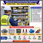
Top 25 Electrical Commissioning Supervisor Interview Questions and Answers forumelectrical.com/top-25-e…
Prepare for electrical commissioning supervisor interviews with 25 essential technical questions and answers covering electrical installation, pre-commissioning inspections, testing procedures, protection systems, switchgear, transformers, cables, earthing systems, and commissioning documentation.
Key topics include:
Electrical equipment inspection and testing
HT/LT switchgear commissioning
Transformer testing and protection
Circuit breaker functional testing
Insulation Resistance (IR) and High-Potential (HV) testing
CT/PT testing and polarity verification
Relay testing and protection coordination
Cable continuity and withstand testing
Earthing resistance measurement
Functional and interlock testing
Pre-commissioning and energization procedures
Method Statements, ITPs, and commissioning reports
Strengthen your technical knowledge, troubleshooting capabilities, site execution skills, and commissioning management expertise for electrical engineering roles.
#ElectricalEngineering #ElectricalCommissioning #CommissioningSupervisor #ElectricalInterview #InterviewQuestions #SwitchgearCommissioning #TransformerTesting #RelayTesting #ProtectionSystems #ElectricalTesting #PreCommissioning #Energization #HTSwitchgear #LTSwitchgear #ElectricalSafety #PowerSystems #ElectricalMaintenance #QAQC #CommissioningEngineer #electricalengineeringjobs
forumelectrical.com/top-25-e…

Electrical Essential Formulas and Unit Conversions forumelectrical.com/basic-el…
Strengthen your technical knowledge with a quick-reference guide covering fundamental electrical engineering equations, electrical quantities, SI unit conversions, and essential power system calculations.
A useful reference for electrical engineering students, electricians, technicians, maintenance professionals, and practicing engineers.
Build a strong foundation in electrical principles, circuit analysis, power calculations, and practical engineering applications through continuous learning and technical practice.
#ElectricalEngineering #ElectricalFundamentals #ElectricalFormulas #ElectricalCalculations #EngineeringKnowledge #ElectricalTechnician #Electrician #PowerSystems #ElectricalDesign #CircuitAnalysis #ElectricalTraining #EngineeringBasics #ElectricalMaintenance #TechnicalKnowledge
forumelectrical.com/basic-el…

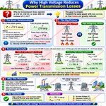
Why Do Power Transmission Lines Use High Voltage? forumelectrical.com/what-are…
One of the most common questions in power engineering is:
Why do utilities transmit electricity at 132 kV, 230 kV, or even 400 kV instead of lower voltages?
High voltage does not increase the transmitted power. Instead, it reduces the current required to deliver the same amount of power.
Lower current means lower transmission losses, higher efficiency, and more economical long-distance power transmission.
Key Takeaway
✅ High voltage is used to reduce current, and lower current results in significantly lower transmission losses.
#ElectricalEngineering #PowerSystems #HighVoltage #PowerTransmission #Engineering #Energy
forumelectrical.com/what-are…

Relay Operating Characteristics in Electrical Protection Systems forumelectrical.com/relay-pr…
Relay operating characteristics define the relationship between fault current magnitude and relay operating time. They are essential for protection coordination, selective fault isolation, and reliable operation of electrical networks.
Main Types of Relay Characteristics:
1. Standard Inverse (SI): Moderately inverse operating time characteristic, commonly used in distribution feeder protection.
2. Very Inverse (VI): Provides faster operation at higher fault currents.
3. Extremely Inverse (EI): Provides a highly inverse response, suitable for applications with significant fault-current variations.
4. Long-Time Inverse (LTI): Provides longer operating times for specific overcurrent protection applications.
5. Definite Time (DT): Operates after a preset time delay when the current exceeds the pickup setting.
Key Relay Parameters:
- Pickup Current
- Time Multiplier Setting (TMS)
- Multiple of Pickup Current (M)
- Operating Time
- Time-Current Characteristic (TCC)
Proper selection of relay characteristics and settings ensures protection coordination, minimizes equipment damage, and improves power system reliability.
#ElectricalEngineering #RelayCharacteristics #IDMT #OvercurrentProtection #ProtectionRelay #RelayCoordination #StandardInverse #VeryInverse #ExtremelyInverse #TMS #EarthFaultProtection #PowerSystemProtection #ElectricalProtection #substationprotection
forumelectrical.com/relay-pr…

Circuit Breaker Sizing forumelectrical.com/acb-size…
Single-Phase and Three-Phase Load Calculations
Correct circuit breaker selection is essential for electrical safety, overload protection, and reliable system operation.
1. Single-Phase Load
Load: 3 kW
Supply voltage: 230 V
Power factor: 0.9
Calculated current: 14.5 A
Current at 125%: 18.1 A
Illustrative breaker selection: 20 A
2. Three-Phase Load
Load: 15 kW
Line voltage: 415 V
Power factor: 0.85
Calculated line current: 24.5 A
Current at 125%: 30.7 A
Illustrative breaker selection: 32 A
Important Technical Considerations
The 125% sizing factor may apply to continuous loads under specific electrical codes and design requirements. It is not a universal rule for every application.
Final breaker selection must consider:
Cable ampacity and installation conditions.
Continuous and non-continuous load requirements.
Overload and short-circuit protection.
Circuit breaker trip characteristics.
Prospective short-circuit current and breaking capacity.
Applicable electrical standards and regulations.
Proper coordination between the circuit breaker and cable ensures safe and reliable electrical installation.
#ElectricalEngineering #CircuitBreaker #BreakerSizing #ElectricalDesign #MEP #ElectricalCalculation #OvercurrentProtection #ShortCircuitProtection #CableSizing #PowerDistribution #ElectricalSafety #ElectricalInstallation #PowerSystems #EngineeringFundamentals
forumelectrical.com/acb-size…

Relay Coordination and Selectivity forumelectrical.com/phase-fa…
Relay coordination ensures that the protective relay closest to an electrical fault operates first, isolating only the faulty section while maintaining power supply continuity to healthy sections.
The three main coordination methods are:
1. Time Coordination: Relays operate with predetermined time delays to achieve selective fault clearance.
2. Current Coordination: Relays use different current pickup settings based on fault current levels.
3. Impedance Coordination: Distance relays detect faults based on measured impedance and predefined protection zones.
Key Technical Considerations:
- Relay pickup current and operating time.
- Coordination Time Interval (CTI).
- CT/PT accuracy and CT saturation.
- Circuit breaker operating and clearing time.
- Maximum and minimum fault current.
- Primary and backup protection settings.
Proper relay coordination improves protection selectivity, minimizes unnecessary power interruptions, reduces equipment damage, and enhances power system reliability.
#ElectricalEngineering #RelayCoordination #Selectivity #ProtectionRelay #OvercurrentProtection #DistanceProtection #CircuitBreaker #PowerSystemProtection #ShortCircuitAnalysis #SubstationProtection #ElectricalProtection #PowerSystems
forumelectrical.com/phase-fa…

Power flow in a Data Centre forumelectrical.com/capacito…
Power flow in a Data Centre is not just about supplying electricity it is about ensuring uninterrupted operations 24/7.
A typical electrical path:
Utility Supply → RMU → Transformer → LV Panel →
UPS → ATS → PDU → IT Racks
Each component has a critical function:
Transformer - Voltage conversion
LV Panel - Distribution & protection
UPS - Clean and uninterrupted power
ATS - Seamless transfer during failure
PDU - Final distribution to racks
Key Design Focus Areas:
✓ Redundancy (N+1/2N)
Load Balancing
Voltage Drop Control
Proper Earthing & Safety
The ultimate goal is simple:
Reliable, Efficient, and Continuous power to IT equipment.
As an Electrical Design Engineer, designing resilience is always the priority.
#DataCentre #ElectricalDesign
#PowerDistribution
#MissionCritical #UPS #Electricalengineering
#DesignEngineer #Infrastructure #MEP
#Engineering #Life
forumelectrical.com/capacito…

kW, kVA, and kVAR in Electrical Power Systems forumelectrical.com/kw-to-vo…
In AC power systems, electrical power is classified into three components:
kW (Kilowatt) – Active Power: The real power converted into useful work, such as mechanical output, heat, and lighting.
kVA (Kilovolt-Ampere) – Apparent Power: The product of RMS voltage and RMS current. It determines the capacity requirements of transformers, generators, and UPS systems.
kVAR (Kilovolt-Ampere Reactive) – Reactive Power: Power exchanged between the source and reactive components to establish and maintain magnetic and electric fields in inductive and capacitive equipment.
Key Relationships:
- Active Power: kW = kVA × Power Factor
- Reactive Power: kVAR = kVA × sin φ
- Apparent Power: kVA = √(kW² + kVAR²)
- Power Factor = kW / kVA
Understanding the relationship between active, reactive, and apparent power is essential for transformer sizing, generator selection, power factor correction, load management, and electrical system efficiency.
Proper reactive power compensation helps improve power factor, reduce current for a given active load, and minimize associated distribution losses.
#ElectricalEngineering #PowerSystems #ActivePower #ReactivePower #ApparentPower #KW #KVA #KVAR #PowerFactor #PowerFactorCorrection #ElectricalFundamentals #PowerDistribution #TransformerSizing #GeneratorSizing #EnergyEfficiency #IndustrialElectrical #ElectricalDesign
forumelectrical.com/kw-to-vo…

Electrical Engineering Interview Questions and Answers forumelectrical.com/electric…
Prepare for electrical engineering interviews by mastering essential technical concepts in power systems, electrical machines, transformer protection, and industrial automation.
Key topics include Ohm’s Law, AC/DC fundamentals, transformer losses, Buchholz relay, transformer oil BDV testing, earthing, power factor, insulation resistance testing, CT/PT, back EMF, star-delta starters, motor slip, synchronous speed, VFDs, and MCCB protection.
Understanding these fundamentals strengthens technical knowledge, troubleshooting skills, and practical engineering competency.
#ElectricalEngineering #ElectricalInterview #InterviewPreparation #ElectricalEngineer #PowerSystems #Transformer #BuchholzRelay #ElectricalProtection #MotorControl #VFD #MCCB #ElectricalMachines #PowerFactor #MeggerTesting #IndustrialAutomation #ElectricalMaintenance #TechnicalInterviews
forumelectrical.com/electric…

Cable Sizing forumelectrical.com/lt-ht-ca…
Selecting the correct cable cross-sectional area is essential for electrical safety, operational reliability, and energy efficiency. Undersized conductors can cause excessive temperature rise, voltage drop, insulation deterioration, and fire hazards.
Cable sizing must consider conductor material (copper or aluminium), design load current, installation method, ambient temperature, grouping and derating factors, permissible voltage drop, short-circuit withstand capacity, and applicable IEC/IS standards.
Never rely solely on approximate ampacity charts. Always verify the final cable size through electrical design calculations and installation conditions.
#ElectricalEngineering #CableSizing #CableAmpacity #CopperCable #AluminiumCable #CurrentCarryingCapacity #VoltageDrop #DeratingFactor #ElectricalDesign #PowerDistribution #ElectricalSafety #IECStandards #ISStandards #electricalinstallation
forumelectrical.com/lt-ht-ca…

Types of Electrical Insulators forumelectrical.com/types-of…
Electrical insulators are essential components of power transmission and distribution systems. They provide electrical isolation between energized conductors and grounded supporting structures while withstanding mechanical loads, electrical stresses, and environmental conditions.
1. Shackle Insulator:
A shackle insulator is primarily used in low-voltage overhead distribution networks. It supports and electrically isolates distribution conductors from poles or cross-arms. It can be installed in horizontal or vertical orientations using suitable mounting arrangements.
2. Pin Insulator:
A pin-type insulator is commonly used in overhead distribution lines, typically up to 33 kV, subject to the insulator design and applicable standards. It is mounted on a galvanized steel pin attached to a cross-arm and provides both mechanical conductor support and electrical insulation.
3. Suspension Insulator:
A suspension insulator is widely used in medium- and high-voltage overhead transmission lines. It generally consists of interconnected porcelain, glass, or composite insulator units arranged in a string. The number of units depends on the system voltage, insulation coordination, and environmental conditions.
4. Line Post Insulator:
A line post insulator is used in overhead distribution and transmission systems, as well as substations. It provides mechanical support for conductors or busbars while maintaining the required electrical clearance from grounded structures.
5. Spool Insulator:
A spool insulator, also known as a shackle-type insulator in certain applications, is commonly used in low-voltage distribution networks. It supports conductors on poles or building structures while providing electrical insulation and mechanical restraint.
6. Stay Insulator:
A stay insulator, also called a guy-wire insulator, is installed in the stay wire supporting utility poles.
7. Strain Insulator:
A strain insulator is designed to withstand high mechanical tensile forces in overhead lines.
8. Busbar Support Insulator:
A busbar support insulator is used in electrical substations and switchgear assemblies.
9. Tubular Insulator:
A tubular insulator is a hollow cylindrical insulating component used in specific high-voltage electrical equipment, including certain bushings and support applications.
#ElectricalInsulators #TypesOfInsulators #PinInsulator #SuspensionInsulator #StrainInsulator #ShackleInsulator #LinePostInsulator #StayInsulator #BusbarSupportInsulator #OverheadTransmissionLines #PowerDistribution #PowerTransmission #ElectricalSubstation #HighVoltageEngineering #ElectricalEngineering #PowerSystems #ElectricalMaintenance #InsulationCoordination #DistributionNetwork #transmissionlineinsulators
forumelectrical.com/types-of…

String Inverter vs. Central Inverter forumelectrical.com/ups-inve…
In a solar photovoltaic (PV) power plant, inverters convert DC power generated by PV modules into grid-compatible AC power. Selecting between string and central inverter architectures depends on installed capacity, PV array configuration, site conditions, grid requirements, system efficiency, and operation and maintenance (O&M) strategy.
String Inverter
- Suitable for residential rooftops, commercial installations, and utility-scale solar projects.
- Each inverter independently processes DC power from multiple PV strings.
- Distributed Maximum Power Point Tracking (MPPT) enables better energy harvesting when different PV strings experience varying irradiance or shading conditions.
- Modular architecture provides greater design flexibility and easier capacity expansion.
- Inverter-level monitoring helps identify faults and simplifies maintenance.
- Failure of one inverter generally affects only its associated PV strings.
Central Inverter
- Commonly used in large utility-scale solar PV installations.
- A single high-capacity inverter processes DC power from multiple PV string inputs, often through DC combiner boxes.
- Centralized power conversion can reduce equipment and installation costs per MW in suitable large-scale projects.
- Requires coordinated DC collection, protection, isolation, and monitoring systems.
- Centralized architecture can simplify plant-level maintenance but creates a larger single point of failure.
- Suitable for large PV arrays with carefully designed string grouping and compatible operating conditions.
Key Technical Considerations
There is no universally superior inverter architecture. String inverters offer modularity, distributed MPPT, and design flexibility, whereas central inverters can provide cost-effective power conversion for large, uniform PV installations.
The final selection should consider DC/AC ratio, MPPT configuration, voltage and current limits, conversion efficiency, clipping losses, partial shading, grid-code compliance, fault isolation, availability, lifecycle cost, and O&M requirements.
Choosing the appropriate inverter architecture helps optimize energy yield, system reliability, maintainability, and overall solar plant performance.
#SolarEnergy #SolarPV #StringInverter #CentralInverter #SolarPowerPlant #PhotovoltaicSystem #MPPT #DCACConversion #SolarEngineering #ElectricalEngineering #RenewableEnergy #InverterTechnology #SolarOandM #PowerElectronics #GridConnectedSolar #SolarPlantDesign #energyefficiency
forumelectrical.com/ups-inve…

2500 kVA Transformer: HT and LT Full Load Current Calculation forumelectrical.com/ht-to-lt…
Accurate transformer full-load current (FLC) calculations are essential for electrical system design, equipment selection, and protection coordination. This technical reference explains how to calculate the rated current on both the High Tension (HT) and Low Tension (LT) sides of a 2500 kVA, 11 kV/415 V, three-phase distribution transformer.
Understanding HT and LT full-load current calculations is fundamental for electrical engineers, MEP design engineers, substation engineers, and electrical commissioning professionals.
#ElectricalEngineering #Transformer #2500kVATransformer #TransformerCalculations #FullLoadCurrent #HTCurrent #LTCurrent #ElectricalDesign #MEPEngineering #PowerDistribution #SubstationEngineering #TransformerImpedance #ShortCircuitCurrent #ACB #MCCB #BusbarSizing #CableSizing #ProtectionCoordination #PowerSystems #ElectricalCalculations
forumelectrical.com/ht-to-lt…

Why are Copper Busbars preferred Over Cables in Electrical Panels? forumelectrical.com/why-busb…
Copper busbars are widely used in high-current electrical distribution systems because of their excellent electrical conductivity, mechanical strength, and thermal performance.
Key technical advantages include:
- High Current-Carrying Capacity: Supports high-current distribution with appropriate cross-sectional area and installation conditions.
- Efficient Heat Dissipation: Provides effective thermal performance when properly designed and ventilated.
- Low Electrical Resistance: Helps minimize resistive power losses and voltage drop.
- Compact Panel Configuration: Enables space-efficient conductor arrangements and organized power distribution.
- Mechanical Strength: Provides rigid conductor support and stable electrical connections.
- Maintenance Accessibility: Facilitates inspection, connection tightening, and modification of panel distribution systems.
Copper busbars are commonly used in Power Control Centres (PCC), Motor Control Centres (MCC), LV switchboards, industrial control panels, and electrical power distribution assemblies.
Proper busbar sizing must consider rated current, temperature rise, short-circuit withstand capacity, ambient temperature, installation arrangement, and applicable electrical standards.
#ElectricalEngineering #CopperBusbar #BusbarSizing #ElectricalPanels #PowerDistribution #PCCPanel #MCCPanel #Switchgear #ElectricalDesign #CurrentCarryingCapacity #ShortCircuitWithstand #ElectricalConductors #IndustrialElectrical #ElectricalMaintenance #EEE
forumelectrical.com/why-busb…
